Splice Electrical Circuit Wires: Safety Tips
Efficiently expand your electrical network by learning how to splice electrical circuit wires. Splice electrical circuit wires like a pro to maximize safety and efficiency in your electrical system. Wire splicing is a commonly employed electrical technique that enables the extension of wires and the addition of devices, all while minimizing the need for extensive drywall demolition and subsequent repairs.
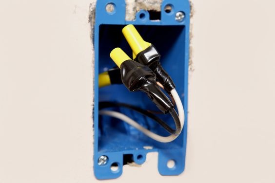
Wire splicing can be performed within the confines of a standard fixture box, which includes outlets or ceiling light boxes. Additionally, wire splicing can be carried out externally to a standard fixture box. In such cases, the cable connections are established within a specifically installed junction box, designated solely for the purpose of wire splicing. This junction box is equipped with a blank cover, providing easy access whenever necessary for work on the wires.
When to Splice Wires
Knowing when to splice wires is essential for various electrical projects. Ideally, it is recommended to have a continuous, uninterrupted cable running from the service panel to the intended device or between devices. This approach offers several advantages, including minimizing the risk of severed wires during emergencies, providing a smoother surface on walls or ceilings, and eliminating any confusion that may arise.
However, there are instances where running a continuous cable is not feasible or practical. This is where wire splicing becomes crucial. By acquiring the skill of wire splicing, you gain the ability to undertake numerous projects that can greatly improve your living space.
Some situations where wire splicing is necessary and useful include:
- Moving an outlet: When relocating an electrical outlet to a different position.
- Moving a light fixture: When changing the position of a light fixture.
- Removing a wall: When demolishing or modifying a wall that contains electrical wiring.
- Finishing a basement: When adding electrical components and connections to complete a basement renovation.
- Dealing with loose wires: When encountering wires that are not properly secured or connected.
- Bringing improperly connected wires up to code: When correcting wiring that does not meet electrical code requirements.
- Branching a circuit into two or more directions: When splitting a circuit to supply power to multiple devices or areas.
- Leaving a junction box in place for future devices: When installing a junction box that will serve as a connection point for future electrical devices or expansions.
Type of Materials to Use
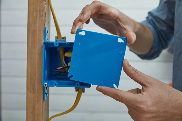
1. Junction Box
When it comes to the type of materials to use for wire splicing, two common options are junction boxes made of plastic and metal.
Metal junction boxes are favored by some electricians due to their durability. However, if you opt for a metal junction box, it’s important to note that it must be connected to the ground system using a grounding pigtail wire. One end of the pigtail wire is connected together with the circuit grounding wires, while the other end is securely screwed directly to the metal box.
On the other hand, plastic junction boxes are also acceptable for wire splicing. Many do-it-yourselfers prefer plastic boxes because they are lightweight, have smoother edges, and the punch-outs for wire entry are easier to remove. Unlike metal junction boxes, plastic junction boxes do not require a grounding pigtail wire.
2. Wire Connectors
Wire connectors play a crucial role in properly splicing electrical wires, and it is important to follow the correct method using UL-approved connectors within an approved electrical box.
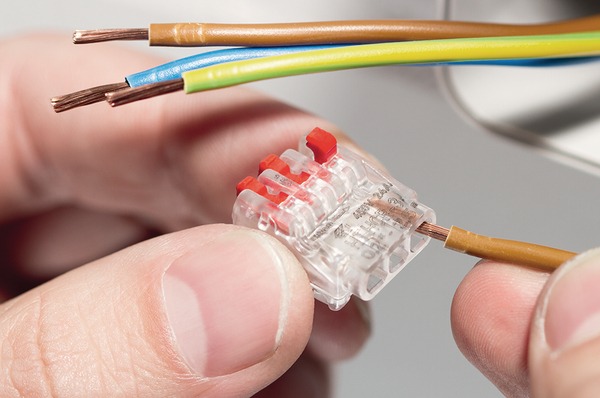
There are two main types of wire connectors commonly used: the traditional twist-on wire nuts and the newer push-fit connectors. Both types of connectors are acceptable and approved by the National Electrical Code (NEC). The choice between wire nuts and push-fit connectors depends on personal preference and the available space within the electrical box. As long as there is adequate room in the box, either type can be used.
It is important to note that the old practice of splicing wires solely with electrical tape should never be employed. Splicing wires with only electrical tape creates a less secure connection compared to using wire nuts or push-fit connectors. Therefore, it is strongly advised against splicing wires with electrical tape.
However, while electrical tape should not be used as the primary splicing method, it is commonly employed to secure wire nuts to the wires, providing an additional layer of stability and insulation.
Safety Considerations
When it comes to wire splicing, safety considerations are of utmost importance. While the technique itself is not overly complex, it is essential for DIYers to possess a solid understanding of electrical systems and have some experience with basic electrical repairs before attempting such tasks.
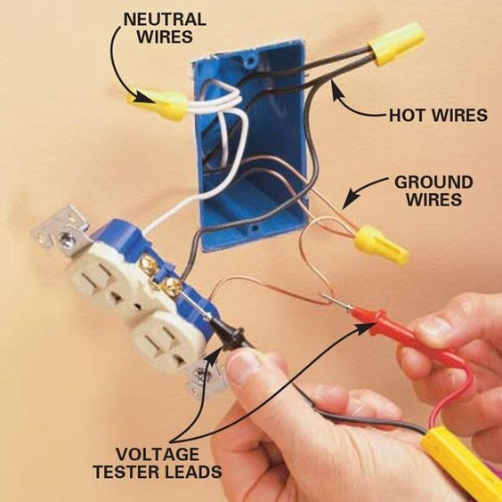
Regardless of the project involving circuit wires, it is crucial to ensure that the power to the respective circuit is turned off at the service panel or breaker box before commencing any work. This precautionary measure helps prevent the risk of electrical shock or other potential hazards.
Furthermore, it is vital to note that electrical splices should never be left exposed within wall or ceiling cavities. Instead, all wire splices must be contained within an approved junction box or fixture electrical box. It is imperative that the junction box remains accessible and is not concealed behind drywall or any other building materials that would require removal to access it. The junction box serves as a protective enclosure, creating a safe environment for the splices. It provides protection against impact and helps contain any sparks or fire in the event of a malfunction. Although junction boxes may initially seem cumbersome or unnecessary, they are designed to be user-friendly and significantly enhance the safety of your work.
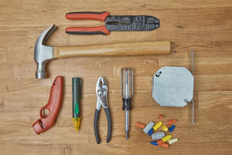
Equipment / Tools
- Cable ripper
- Wire stripper
- Hammer
- Screwdriver
- Pliers
- Cordless drill with driver bit
- Drill bit extender
Instructions for Splice Electrical Circuit Wires
The instructions provided here assume that the walls are accessible, allowing for easy access, and that the electrical cables have already been installed within the wall cavities. If the cables have not been run inside the walls, the process of fishing the cables through the walls will add complexity and additional time to the project.
Examine Wiring:
Before proceeding with the wire splicing, it is crucial to ensure that you are joining two similar cables. These cables need to match in terms of wire gauge and the number of individual conductors they contain. For modern wiring, typically up to 50 years old or so, this information is often printed on the outer sheathing of the cable.
For instance, a cable labeled as “12/2 w ground” indicates that it contains two 12-gauge insulated conductors along with a bare copper grounding wire. It is essential to verify that both cables to be spliced have the same gauge and number of conductors, ensuring compatibility and safe electrical connections.
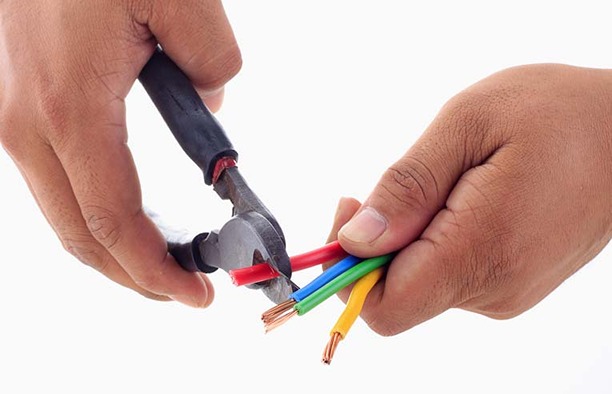
Remove the Outer Sheathing from the Cable:
To expose the individual conducting wires within the sturdy outer plastic jacket of the cable, follow these steps:
- Use a cable ripper instead of a utility knife to avoid the risk of accidentally cutting into the individual wires. Insert the cable into the designated hole on the cable ripper, ensuring it goes in about 6 inches from the cable’s end.
- Gently press the sides of the cable ripper together and carefully draw the tool off the end of the cable. This motion will slice through the sheathing, allowing access to the wires inside.
- Once the sheathing is cut, remove the severed portion along with any paper filler. You can accomplish this either by using the cutting jaws on a wire stripper or by employing a utility knife to trim away the unwanted section. Exercise caution to avoid damaging or nicking the individual wires during this process.
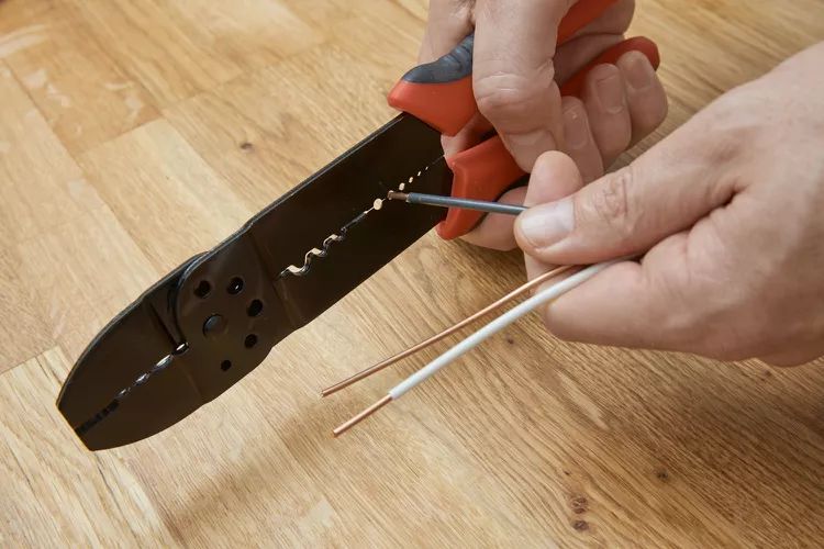
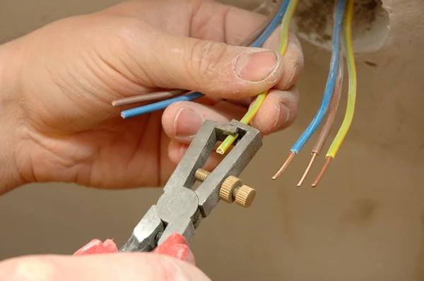
Strip Insulation from Conductors:
Within the cable, each conducting wire, excluding the ground wire, is coated with plastic insulation in different colors. Follow these steps to strip approximately 1/2 inch of insulation from each wire:
- Utilize a wire stripper tool designed for this purpose. The wire stripper tool contains slots that correspond to various wire gauges. Select the appropriate slot that matches the gauge of the wires in your cable.
- Place the wire into the matching slot on the wire stripper tool, ensuring that the insulation is within the designated stripping area.
- Gently squeeze the handles of the wire stripper tool, applying enough pressure to grip the insulation but not to damage the underlying conductor.
- With the pressure maintained, carefully pull the wire stripper tool along the length of the wire, moving away from the end. This action will cut through the insulation without harming the conductor.
- Release the handles of the wire stripper tool and gently twist the wire to separate the stripped portion of the insulation from the wire.
Inspect the Cables:
Before proceeding with the wire splicing process, carefully examine the wiring on both cables for any indications of damage. Look out for the following signs:
- Damaged insulation: Check for any cuts, chewed sections, or signs of burned insulation on the cables. If you notice any of these issues, it is crucial to address and rectify them before proceeding further.
- Nicked wiring: Inspect the wires within the cables to ensure they are free from nicks or cuts. The wire insulation should be intact and smooth along their length.
For properly prepared cables, approximately 6 inches of wire should extend beyond the edge of the remaining cable sheathing. Additionally, the individual wires should be stripped back to expose the necessary length of conductor, and the stripped sections should be smooth without any damage.
Taking the time to thoroughly inspect the cables ensures that they are in proper condition for the wire splicing process. If any damage or issues are identified, it is essential to address them before proceeding to maintain the integrity and safety of the electrical connections.
Remove Knockouts from Junction Box:
To create openings in the junction box for cable entry, follow these steps:
- With a screwdriver and hammer, loosen two knockout disks that are opposite each other on the junction box. These disks are typically marked with perforations to facilitate their removal.
- Use a pair of pliers to carefully pry off the loosened knockout disks. Apply gentle pressure and work around the edges of the disk until it comes free from the junction box. In some cases, you may need to rock the disk back and forth several times to dislodge it completely.
- Once the knockout disks have been removed, discard them appropriately.
By removing the knockout disks, you create openings in the junction box that allow for the entry of cables. This step is necessary to accommodate the wires and facilitate proper wire splicing within the junction box.
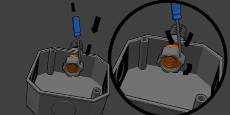
Attach Cable Clamps to the Junction Box:
To secure the cables in the junction box, follow these steps:
- For plastic cable clamps, they typically feature a design that allows them to easily snap into the knockout openings in the junction box. Simply align the clamp with the desired knockout opening and firmly press it into place until it securely snaps into position.
- For metal cable clamps, begin by removing the threaded tightening ring. Once the ring is removed, insert the clamp through the knockout opening in the junction box. Ensure the clamp is positioned correctly.
- From the inside of the junction box, screw the tightening ring back onto the clamp. Use pliers to firmly tighten the ring, ensuring a secure connection. Be cautious not to apply excessive force while tightening, as this could potentially break the clamp.
By attaching the appropriate cable clamps to the junction box, you effectively secure the cables in place, preventing them from being pulled or accidentally dislodged. This step helps to maintain the integrity of the electrical connections within the junction box.
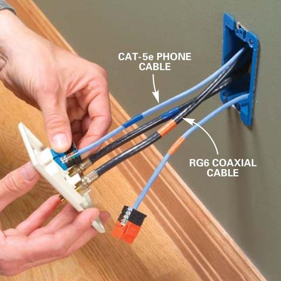
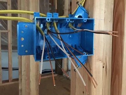
Insert the Cables:
To properly insert the cables into the junction box, follow these steps:
- Begin by selecting the appropriate knockout in the junction box for each cable. Insert one cable into each knockout, ensuring they pass through the corresponding cable clamps. Take care to position the cable flat on the clamp’s surface. Avoid accidentally positioning it sideways, as this could lead to damage to the cable itself.
- As you insert the cables, ensure that the sheathing of each cable extends beyond the clamp and into the box by approximately 1/4 to 1/2 inch. This allows for proper cable management and secure connections within the junction box.
- For plastic cable clamps, they typically feature a tab that you can force closed to grip the cable securely. Press down on the tab to engage it, providing a firm grip on the cable.
- In the case of metal clamps, use a screwdriver to tighten the screws on the clamp. Gradually tighten the screws until the cable is securely gripped by the clamp. Take care not to overtighten, as this could cause damage to the cable or the clamp itself.
By properly inserting and securing the cables within the junction box, you ensure reliable connections and prevent any accidental dislodging or damage to the cables during use.
Attach the Box and Cover Plate:
To securely attach the junction box and cover plate, follow these steps:
- The junction box is equipped with holes in the back and sides, allowing you to screw it to a wooden framing member. If needed, you can use a bit extender with a drill to facilitate driving screws without disturbing the wires. This can provide easier access to the screw locations.
- Ensure that the junction box is firmly attached to the framing member. Choose a depth that will allow the cover plate to fit securely over the box once the wall or ceiling surface is finished. For instance, if you plan to use 1/2-inch drywall for the finished surface, the front edge of the box should extend approximately 1/2 inch beyond the front face of the stud. This positioning will ensure that the box aligns flush with the finished wall or ceiling surface.
By properly attaching the junction box and cover plate, you ensure a secure and stable installation. This step ensures that the box will be securely mounted within the wall or ceiling, allowing for the safe and convenient use of electrical devices or connections.
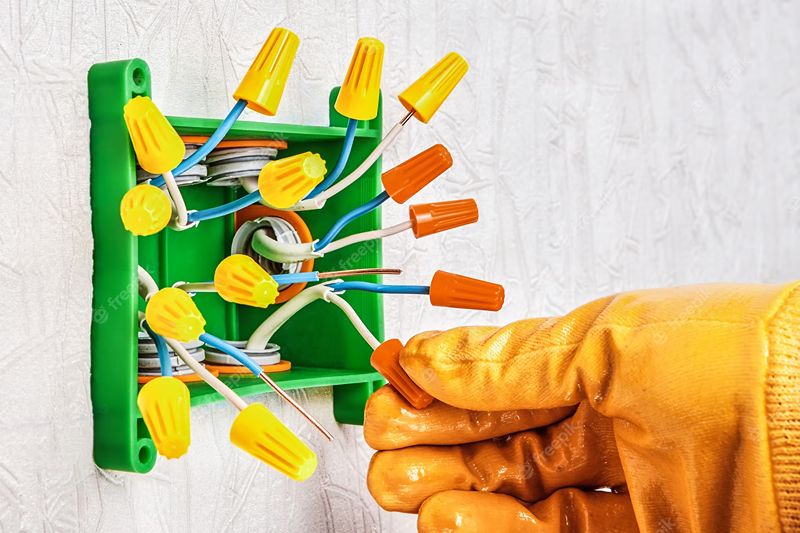
Make the Wire Connections:
To properly connect the wires, follow these steps:
- Utilize approved wire connectors to join the conducting wires that have similar insulation colors. Ensure that the connectors are suitable for the specific application and comply with safety regulations.
- If using standard wire nuts, there are different methods of making the connections. Some electricians prefer to twist the wires together using pliers before screwing the wire nuts over the ends. However, some wire nut manufacturers provide instructions to simply hold the parallel wires together and twist the wire nut over the bare ends in a clockwise direction. Whichever method you choose, ensure that the wires are securely connected to the wire nut, capable of withstanding a slight tug without coming loose. Confirm that there are no exposed bare wires at the bottom of the wire nut. Some electricians may also choose to reinforce the wire connection by wrapping a loop or two of electrician’s tape around the base of the wire nut and wires.
- Another approved type of wire connector is the push-fit connector. These connectors feature grip-fit sockets, where you can simply insert the bare end of the wire into the appropriate socket to establish a secure connection.
- The bare copper circuit grounding wires should also be connected together within the junction box using an approved connector. In the case of metal electrical boxes, run a third grounding pigtail (bare copper or green insulated) from the two bare copper circuit grounding wires. Connect the free end of the pigtail to a threaded screw opening on the metal box using a green grounding screw. This method effectively grounds the electrical box, enhancing the overall safety of the circuit.
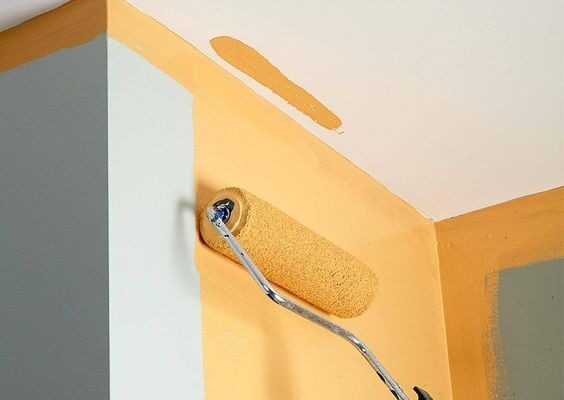
- Once the wire connections are completed, proceed to finish the wall or ceiling surface around the junction box. Afterward, securely attach the cover plate to the box. Some cover plates have a matte surface that allows for painting, providing flexibility in matching the surrounding decor.